
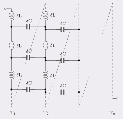
Fig.1 A possible distributed element model of an inductor
A more accurate model will also require series resistance elements with the inductance elements. An example where a simple one-dimensional model will not suffice is the windings of an inductor. Coils of wire have capacitance between adjacent turns (and also more remote turns as well, but the effect progressively diminishes). For a single layer solenoid, the distributed capacitance will mostly lie between adjacent turns as shown in figure 1 between turns T1 and T2, but for multiple layer windings and more accurate models distributed capacitance to other turns must also be considered. This model is fairly difficult to deal with in simple calculations and for the most part is avoided. The most common approach is to roll up all the distributed capacitance into one lumped element in parallel with the inductance and resistance of the coil. This lumped model works successfully at low frequencies but falls apart at high frequencies where the usual practice is to simply measure (or specify) an overall Q for the inductor without associating a specific equivalent circuit.
In electrical engineering, the distributed element model or transmission line model of electrical circuits assumes that the attributes of the circuit (resistance, capacitance, and inductance) are distributed continuously throughout the material of the circuit. See figure 2 ,this is in contrast to the more common lumped element model, which assumes that these values are lumped into electrical components that are joined by perfectly conducting wires. In the distributed element model, each circuit element is infinitesimally small, and the wires connecting elements are not assumed to be perfect conductors; that is, they have impedance. Unlike the lumped element model, it assumes non-uniform current along each branch and non-uniform voltage along each node. The distributed model is used at high frequencies where the wavelength becomes comparable to the physical dimensions of the circuit, making the lumped model inaccurate.
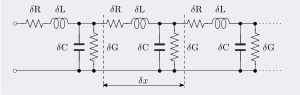
Fig.2 The distributed element model applied to a transmission line
Method of reducing the distributed capacitance
The equivalent capacitor between turns and turns of the coil, coil and shield, coil and board called distributed capacitor. The existence of distributed capacitance reduces the Q value of the coil, and the stability becomes worse, The existence of distributed capacitance will increase the resistance of the coil's equivalent total loss, and the quality factor Q will decrease ;so the distribution capacitance of the coil should be as small as possible. The distributed capacitance can be reduced by using the method of subsection winding..
High frequency coil often use honeycomb winding method, namely, let the wound coil, the plane is not parallel with the plane of rotation, but intersection with the certain angle, the coil called honeycomb coil. Rotation of the coil one circle, bending times of the wire back and forth, known as the number of nodes. The honeycomb winding method has the advantages of small volume, small distributed capacitance, and low inductance. The more nodes , the smaller the distributed capacitance .
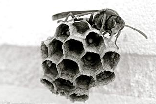
Figure 3 Structure of honeycomb
 Pre:
Pre:  Next:
Next: