
Leakage inductance derives from the electrical property of an imperfectly-coupled transforme rwhereby each winding behaves as a self-inductance constant in series with the winding's respective ohmic resistance constant, these four winding constants also interacting with the transformer's mutual inductance constant. The winding self-inductance constant and associated leakage inductance is due to leakage flux not linking with all turns of each imperfectly-coupled winding. See figure 1 .
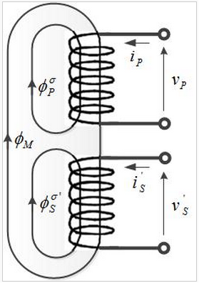
Figure 1 Magnetizing and Leakage flux in a magnet circuit
The leakage flux alternately stores and discharges magnetic energy with each electrical cycle acting as an inductor in series with each of the primary and secondary circuits.
Leakage inductance depends on the geometry of the core and the windings. Voltage drop across the leakage reactance results in often undesirable supply regulation with varying transformer load. But it can also be useful for harmonic isolation (attenuating higher frequencies) of some loads.
Although discussed exclusively in relation to transformers in this article, leakage inductance applies to any imperfectly-coupled magnetic circuit device including especially motors
How to reduce the leakage inductance
Lower leakage inductance can be obtained as below method
1.Each set of windings must be tightened, and the distribution should be evenly coiled.
2 lead of winding, as far as possible at right angles, close to the wall of bobbin.
3 When windings is not full for one layer , should be evenly wound on one layer of Bobbin.
4 Insulation layers between windings should be as less as possible.
5 If the space is enough, can use longer bobbin, reduce the thickness of bobbin
For multilayer coil, in the same way, the magnetic field distribution of the more layer coil can be made. In order to reduce the leakage inductance, the primary and secondary segments can be segmented. For example, the primary 1/3 first, secondary 1/2, then primary 1/3, secondary 1/2, primary 1/3 or primary 1/3, secondary 2/3, primary 2/3, secondary 1/3, etc., the maximum magnetic field strength is reduced to 1/9. Sandwich winding method is popular, see figure 2 as below. However, the coil is too many, winding process is complex, the distance between primary and secondary windings increased, the filling coefficient of bobbin decreases, while the primary and secondary shielding become difficult.

Figure 2 Sandwich Winding method
If the output and input voltage is low, and leakage inductance is very small, such as driver transformer, can use the bifilar winding, and at the same time, the wider window and longer height of the magnetic core, like a tank type, the RM type, PM ferrite magnetic core, so that the window in the magnetic field strength is very low, to obtain smaller leakage inductance.
 Pre:
Pre: